Wednesday, March 17, 2010

Noiseless measurement of Optical Signal and Laser Pulse generation

After one week of thinking my project is finally decided its "Noiseless measurement of Optical Signal and Laser Pulse generation". Deciding the project was tough job, not only I had to consider that the project should be complited in three weeks it should also not very complicated as well as not very simple. I had many thoughts in mind like making "MP3 player", "USB pen drive", "Touch screen " or "Laser guided robot" but I did'nt like any of them very much since they are mostly electronics gadgets, available in market ( and if you respect chines they can be really very cheap) also I am Physicist not an electronics engineer. Electrnics is just happend to be my hobby but Physics is my passion. So I wanted to decide some project which will reflect my Physics background and finally came up with this Idea.


Motivation-
Often during optical measurment background light is a big problem (still remember the complite blackout of optics lab ). I decided to come up with the idea to remove this background light noise. The idea is as follows-
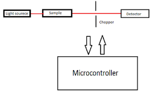
  1. Light from the light source ( usually laser , monochromator ) is allowed to pass through sample and chopper on to the detector. The job of the chopper is to periodically allow and block the light from the light source. In this way the detector will receive two kinds of signals one with (laser + background ) and other with only background light. Now I just need to subtract these two signals to remove the noise.
  2. Second part of the project is generate laser pulse of desired pulse width of order of millisecond. The idea is to control the speed of chopper motor using PWM method. A feedback mechanism is used to continuously monitor the speed of the chopper motor and then use this data and the set value of pulse width to control the speed of motor.
Part List-
  1. Any 80C51 core micro-controller (I am using P89V51RD2).
  2. LDR ( Light dependent resistor ) as detector.
  3. Chopper and opto-coupler (soon going to post the picture of my opto-coupler ).
  4. LCD.
  5. Keyboard.
I will keep posting the development in the project. I have got three weeks to complete this project lest see how I do .


Update 16 April :
Finally got some time to write.
I started with interfacing LDC to microcontroller. I have written a nice code library for interfacing it. Then I switched to interfacing ADC. I used 8080ADC. Instead of  using external clock using say 555 I used the clock generated by the uC itself. The ADC worked perfectly fine. I landed up in making a simple voltmeter by interfacing the LCD and ADC together. Till now everything was fine but later I observed that ADC is too slow for my use (data sheets says 100us for each conversion ) so I had to ditch the entire Idea of using ADC and I switch to atmega16 which has internal ADC with 15ksps. It was frustrating as my design was completly ready and now I have to start from scrach. Any was I switched to atmega16 all the software development is completed and its working fine atleast in simulation. I will implement it in hardware later.

Sunday, March 7, 2010

What really happened on Mars?

I remember when I was a kid probably in 6th or 7th grade our principle ma'am gave as a example in our daily morning assembly program. Since I was very tall among other class mates I was standing at the end of the line and was really strugling hard to listen her. She was talking about some billion dollar project which was failed just because of some error of 1 and 0. She further told as that Nasa has sent a spacecraft to mars and the robot is male functioning just because of some mistake in 1 and 0. Well at that time I was thinking how come a signle sweep in the digit of 1 and 0 can cause the whole project to crash. Although I didn't understood anything at that time but I was very much fascinated by the whole Idea of sending a bot to Mars. I read each and every article I found in paper regarding the Mars Project but most of them didn't satisfied my needs.
After very long time when I was in 12th standard and my physics teacher taught me digital electronics I understood something what my principle ma'am was taking about. Now I understood what she was talking about I knew that it has something to do with the Boolean condition. Now I am in fourth year of my graduation in IIT Bombay and It took me almost 12 years to understand what really happened in Mars.

So here we go-

The Mars Pathfinder mission was widely proclaimed as “flawless” in the early
days after its July 4th, 1997 landing on the Martian surface. The spacecraft has to gather the meteriological data and send them back to earth. The spacecraft has one processor and has to do many process at time. The engineers decided to in manner called "preemptive priority scheduling of tasks". By tasks I mean process like gathering data or communication with earth.
The operating system is designed such that It after every fixed amount of time (time slice ) the OS will look for all process and assign priority to every process in every cycle and execute process with highest priority.

Pathfinder has mainly three tasks low priority "meteorological data gathering" which run infrequently , medium priority "communication task" and high priority "information bus management task" which run very frequently. The information bus can be assumed as the common memory used by every tasks to exchange information and hence bus management task should run very frequently. Access to the bus was synchronized with mutual exclusion locks called mutexe which will insure that bus is locked to a particular task and other tasks can't access the bus.

How it works-

The meteorologica task will run , it will collect data and while communicating with earth It will access the information bus through mutexes which will lock the bus. Now if an interrrept occur and Information bus is needed to be accessed the Bus management task will wait till the bus is unlocked by mutexe. Once bus is released the Bus management task will use it.

The bug-

Suppose the Bus is locked by the meteorological data task and bus management task is waiting for the bus to be released. At this point of time if interrupt occur that causes the "communication task" to be scheduled with high priority. The OS will keep the "meteorological task" at hold (waiting ) and will start running slow "communication task". Now the communication task is running and "meteorological task" is waiting which has unfortunately locked the Information bus and the highest priority "Information bus management task " is still waiting to access bus. After some point of time if Information bus management task didn't get to access bus "watch dog timer" thinks that something is terribly wrong with system bus and call for Total System Reset.

So where is 1 and 0's-

Now the mutex object accepts a boolean parameter that indicates whether priority inheritance should be performed by the mutex. The basic idea of the priority inheritance protocol is that when a job blocks one or more high priority jobs, it ignores its original priority assignment and executes its critical section at the highest priority level of all the jobs it blocks. After executing its critical section, the job returns to its original priority level. Before launching the pathfinder mutex was initialized with this parameter OFF. So here comes the 1 and o mistake if had it been initialized with this parameter ON the mutex could have released the information bus locked my meteorological task for bus management task which in turn could have prevented watchdog timer from invoking total system reset.

So was it debugged ?

During the development stage of Pathfinder the OS has a C language interpreter intended to allow developers to type C expressions and functions to be executed on the fly during the system debugging. Fortunately Pathfinder was launched with this feature still enabled. A C program was uploaded to the spacecraft, which when interpreted, changed the values of the initialization variable of mutex form FALSE to TRUE. There was no system reset after that.

Saturday, March 6, 2010

Mountain First Aid

Note-For educational purpose only, professional advice should be taken before going to life threatening situation
First Aid person should be experienced

Seven steps to follow after accident -

Step-1:Take the charge of the situation.
  1. If more then one person is injured the order of priority,
    1. More injured but good change of survival should be given first priority.
    2. More inured but can wait.
    3. Who can do safety treatments.
    4. Less chance of survival.
  2. Climb leader should survey the seen immediately.

Step-2:Approach the patient safely-
look for rockfall, avalanche, fast water flow and physical limits.

Emergency rescue and fist aid-
Shift the person if he is in danger or the rescuer is in danger otherwise first inspect the injury. Watch for -
  • Alertness
  • Response of your call.
  • Responsive of pinching (semiconscious )
  • Unconscious.
If semiconscious or Unconscious check for ABCD-
A- Airways ( see nose and mouth ). If there is clothing of blood in nose or swelling in mouse. First clear the airways.
B-Breathing - put hand in front of nose or put small peace of cotton in front of nose.
C- Circulation - normal is 60-90 pulse rate. Pulse rate increases during unconsciousness and can go up to 180 . Observe the pulses from neck since hands will be covered with gloves etc.
D- Deadly bleeding -
External bleeding or internal bleeding.
If internal bleeding check for important sites
  1. Abdomen -
    tightness and swelling at abdomen.
  2. Thai -
    -swelling , blueish color and stiffness at thai.
    -Pulse rate will be very high but less powerful pulse or low pulse pressure.
    - Due to internal bleeding patent can go to comma . Immediately shit patient to hospital.
Step-4:Protect patient-
CPR http://depts.washington.edu/learncpr/quickcpr.html and Cardio.

Step-5
Provide dry clothes, pain killers, shelter and psychological support.

Step -6:Check for other minor injuries-
From head to legs- ears , eyes , teeths , redness at eye or readness at the bottom of eyes, check head, spinal injury (important - if injured stifness ), discolour of skin any defromity (visible fractures ) , swealing ( don't take chance it can be fracture )

Important thing to note-
fracture , spinal and head injury.

Fracture-
-don't move patent too much.
-tie with stick, thick clothes, newspapers since it give painless moment to patient.

Step-7:Carry out plan-
First aid leader will plan for further treatment and climb leader will plan for rest of party.If needed shift the person to base camp with a note detailing his injury . Strong person should shift the patent. Climb leader will decide whether to go further , wait for rescue or come back.

Mountain Manners

Set of rules and regulations that a tracker should follow.

1) Greetings-
Respect other trackers and local peoples, wish them in there local languages say hi, hello.

2) Walking Manners-
-single line don't overtake.
-rythmatical walk- All team should reach at time
-Week person must be in middle of line

3) Judging distance-
1 hour or 2 hour walk according to our capacity.

4) Passing Information-
through arrows or cairns ( heap of stones ) for people coming behind you so that they will not miss the track.

5) Noise Behavior-
-snow bridge can collapse.
-wild animal can attack because of fear.
-Avalanche.
-Rock fall may happen.

6) Hut manners-
When using forest guest houses or huts maintain cleanliness and don't leave any sigh after you leave.

7) Conservation of flora and fauna
-Respect wild animals.
- vegetation ( don't plug flowers etc because they can be dangerous.)

8) Camping manners-
-Camps and tent's must be near drinking water.
-Tents shouldn't be very near to river. ( because in some area river level changes in 5 min also (flash flood )).
-Should not be very near to rock fall area.
-Should not be very near to avalanche prone area.

9) Rescue and search-
Rescue for living person and search for dead person.

Do's and Don't-

1)Do's-
  • Planning (transport, food , climate, rescue ) and preparation.
  • Layout all the equipments (List of equipments ).
  • Select experienced leader accepted by all.
  • Management of rescue
    - chopper ( helicopter arrangement )
    -Bone break arrangement.
  • Greeting.
  • Walk in single line and rythmatical walk.
  • weak or injured person in middle of line.
  • Respect culture and religion of the place and local peoples.
  • Keep survival kit (dry foods etc used if lost ) and first aid kit with you.
  • Follow hut manners.
  • Conservation of flora and fauna.
  • Respect wild life.
  • Passing massage (use bushes to show direction or cairn ).
  • Pass bridge one by one.
  • Construction of bridge if needed.
  • Obey the order of leader and respect the leader.
  • Proof of ascent like photographs or videos.
2) Don'ts-
  • Don't go alone.
  • Don't make noise
  • Don't put too heavy load.
  • Don't disturb wild life, flora and fauna.
  • Don't through stones.
  • Don't thorough waste materials.
  • Don't smoke and use alcohol.
  • Don't pollute water resources (as you will drink that water in future).
  • Don't neglect minor injuries.
  • Don't make loose talk ( in mountain sickness you loose your temper, abnormal behavior ).
  • Don't touch unknown flowers.
  • Don't be over confident.
  • Don't disturb public or private properties.
  • Don't rest (during walking ) from where you can't see your partners.
  • Do not avoid week persons.

Mountaining Hazards

Types of mountaineering hazards.-
  1. Objective Hazards - Hazards created by power of nature.
  2. Subjective Hazards and Psychological Hazards - Hazards by mistake of climbers ( Human Hazards )
Objective Hazards-

1) Weather-
  • Whiteout-
    If unknown place wait for clear. If distributed use torch for signaling (distance signaling).
  • Lightning-
    -keep away from metals.
    -conical rock (at the top of the mountain) has no snow. During lightining come to the place covered with ice and away from rock.
    -Don't take shelter at conical rock and below single tree.
  • Snow Blizzards-
    snow comes with wind.
    -wait till it get clear.
    -blizzards can enter your nose or ears or shirt.
    -stand opposite to it.
  • Snow fall or rain fall-
    -pack all items in plastic bags.
2) Avalanche-
Mass of snow slide down from mountain to valley side.

3) Land Slide-
- start form beginning.
-pass one by one (other should watch and told passing person)
-select best way.
-don't pass without helmet or use rucksack to protect head.

4) River and streams-
streams are dangerous, they are small but flow can be from
8km/h to
km/h

5) Glacier-
moving river of ice.

6) Cornice (very dangerous )-
over hang lap of snow stuck on the mountain ridge.
- crup with X- stick to check hollowness
- choose central or middle area.

7) High altitude sickness-
irritation, noise beading , breathing problems.
-Acclimatise body then climb.

Subjective Hazards-

1) Sun burn -
Use caps, cover , suns scream, hats, umbrella.

2) Snow blindness-
-At mountain UV rays reflect from snow and enter to eye.
-Use black goggles.
-If suffering from snow blindness then use water or urine.
symptoms of snow blindness-
-feel irritation in eyes.
-eye turn to reddish.
-tears comes.

3)Frost Bite-
Blood tissue die because of cold
-don't use wet gloves, socks and always cover face (nose and ears).
Symptoms-
-chill burn
-skin color change to red then yellow then blue.

4) Benightment-
spending night without food, shelter and equipments. Without proper plan or co-ordination in team.

5) Fall and slip and over confidence-
-Use proper sole shoes.
-Concentrate on work.

6) Team Management-
Choose the root such that week person can also climb.


Friday, February 5, 2010

Installing Ubuntu 9.10 in Vista using VirtualBox

Often we need some software which are opensource and run in linux OS only. Dual booting your machine with Windows and Linux is one option. But just for one software switching between two OS is not desirable since we need to restart the machine every time. The best way out is to install Linux OS like Ubuntu in windows itself. To do this follow the steps-
  1. Download and install VirtulBox. (http://www.virtualbox.org/wiki/Downloads).
  2. Open virtual box. Select New. In OS select Linux from drop down list and then select Ubuntu.
  3. Set the desired setting. It is desirable to give more RAM to virtual machine if you have RAM most of the time remains unused.
  4. For hard disk you can either select static or dynamic drive. Dynamic drive is desirable.
  5. Once all set select the machine and start for the first time mount the iso file of ubuntu desktop edition.
  6. Machine will boot on it and follow the normal ubunut installation instructions.
  7. After installation the machine will restart and you will see ubuntu inside the vista.
  8. Ofter the screen size is fix and usually set to 800x600 which is not desirable.
  9. Go to device -> Install device addons.
  10. A cd rom will appear in your Desktop of VM (virtual machine). Run the following
    cd /cdrom
    sudo ./VBoxLinuxAdditions-x86.run
  11. Once addon installation done press Ctrl+F and then Ctrl+G. Your are done. Enjoy

Thursday, February 4, 2010

8051 Microncotroller

It is a good idea to start with the simple and most popular microcontroller 8051. The controller I am going to use is from Atmel AT89S52 microcontroller. I will start with small introduction then Assembly programing then we will use nice C compiler for programing. It cost around Rs60 and has some great features like-

Introduction

The AT89S52 is a low-power, high-performance CMOS 8-bit microcontroller with 8K bytes of in-system programmable Flash memory.

Specifications

  • Compatible with MCS®-51 Products
  • 8K Bytes of In-System Programmable (ISP) Flash Memory
  • Fully Static Operation: 0 Hz to 33 MHz
  • 256 x 8-bit Internal RAM
  • 32 Programmable I/O Lines
  • Three 16-bit Timer/Counters
  • Full Duplex UART Serial Channel
  • Fast Programming Time
Before starting it is a good idea to get familiar with internal architecture of the microcontroller.

8051 family of microcontrollers are based on "modified Harvard Architecture" which means we have different memory location for data and instruction.

  1. It has internal RAM to store data and Flash memory to store Instructions. Pins are provided to attach external RAM and ROM to the microcontroller. Separate address space is used to access both memory (as well as internal and external )which is encoded in instruction itself.
  2. Bit wise addressing is also possible.
  3. The upper part of memory consist of SPR (Special Purpose Registers)
Hardware Required
  1. AT89S52 microcontroller.
  2. Crystall

Friday, January 29, 2010

Microcontroller and Embedded System Design

Introduction to my microcontroller and Embedded System Design Blog
For last two years I am working on microcontroller and embedded system design. I have worked with 8051, Atmega16/32, PIC 18F4550 (for USB) and will be working on ARM. I have little experiance on CPLD and will learn FPGA in this semester only. So I decided to start this new blog series related to microcontroller. For the starting I will use 8051. Architecture and assemble programming. After that I will switch to embedded C. Once we are done with 8051 we will move on to more complex microcontroller. Learning microcontroller is great fun. You can see the fruits of your labor. I hope that I will be able to give something which will benefit someone.

Home made C-V measurment system

My dual degree project is fixed and I am going to work on Nano devices. So surely I will be doing some HEMT fabrication and there characterization. Most common of electrical characterization is C-V measurement at different frequencies. So first challenge is measuring Capacitance (C) of the device. We had C-V measurement system in our lab but unfortunately it is shifted to electrical department and I am not in mood to go to EE department every time I want to do my measurements. Setting up a new CV setup is costly, A LCR meter from Agilent itself cost Rs 9 Lakh and we are not in mood of spending money on it. So I decided to make our own C-V measurement setup. Now I know some of methods which are used to measure capacitance.
  1. Charge the capacitor with constant current source and then see how the voltage changes across the capacitor. Assuming ideal capacitor we can find capacitance equal to current / (time rate of change of voltage ). Well this method is simple but not accurate and many multimeter uses this method and there are very cheap so I am not going to this method.
  2. Apply an AC signal across the RC circuit. Measure the voltage across the resistor or capacitor. The phase shift , amplitude difference between these signals will give as value of the capacitance. This is the method which is widely used in the more sophisticated instruments which cost lakhs. So I am going to use this method.
Now after deciding my method I am going to need some instruments. I made some circuits for both signal generator and aquaring data of voltage drop across the resistor. But since I need more sophisticated instrument I decided to use the Tektronix AFG3000 signal generator and Tetronix TDS1012B oscilloscope both of the instrument is available in my lab. I am going to use matlab for the data controlling the signal generator and acquiring the data from the oscilloscope. A Graphical user Interface will be made so that user can choose range of capacitance measurement and other tasks. This is what I have done so far , I will update the blog as I will go through the project

Saturday, January 23, 2010

Home Made PCB using Toner Transfer Method

Making a circuit , soldering all components connecting them using wires etc are always been very painfull to me. So I came up with this solution of making PCB in home. In india it is really very difficult to find some shops from where you can get ready made PCB. Even if you find some shop (like i found one ) it will be very time taking ( you have to give order and then wait till it get ready and usually take one week or so ) and costly. So here we go.

Check list before you start.
  1. Glossy paper (the one used for photoprinting and can be bought from any photostudio).
  2. Blank copper PCB.
  3. Ferric Chloride.
  4. Acetone and Isopropenol (optional)
  5. Liquid tin

Steps to follow-

  1. First clean the PCB inorder to remove dust and oxides. You can clean it with VIM. (optionally you can clean it with iso proply alchohol).
  2. Design you layout using the eagle software (you can download the free version just google it).
  3. Take the printout of the circuit layout (mirror image) in the glossy paper.
  4. Now heat up the iron, put the PCB on table and pre heat up it with iron and printed glossy paper on top of it heated PCB, be careful because the glossy paper will stick on the PCB so you have got only one chance to place the paper carefully.
  5. Now put normal paper on top of the glossy paper and use iron to further heat. Put pressure so that the print get transfer to the PCB.
  6. Once done with above step , let the PCB cool for some time to normal temperature and then put it in the water. Glossy paper will can now easy be removed from PCB just using thumb. After removing the glossy paper you can clearly see the Print on PCB.
  7. Now take some Ferric chloride solution, heat it to 70 degree and then put the PCB in the solution and stair it for some time. (handle with care it is dangerous , avoid direct contact with skin - use mask and gloves).
  8. You will see that the copper where the print is not there is been removed. Use window cleaner or nail polish cleaner to remove the remaining black print in PCB. (optionally you can use acetone or ask the printer guy the solution he uses when his clothes get dirty with the colors ).
  9. Now you are left with the clean PCB with circuit treks in it. To avoid oxidation and good soldering use dip the PCB in liquid tin