Motivation-
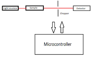
Often during optical measurment background light is a big problem (still remember the complite blackout of optics lab ). I decided to come up with the idea to remove this background light noise. The idea is as follows-
- Light from the light source ( usually laser , monochromator ) is allowed to pass through sample and chopper on to the detector. The job of the chopper is to periodically allow and block the light from the light source. In this way the detector will receive two kinds of signals one with (laser + background ) and other with only background light. Now I just need to subtract these two signals to remove the noise.
- Second part of the project is generate laser pulse of desired pulse width of order of millisecond. The idea is to control the speed of chopper motor using PWM method. A feedback mechanism is used to continuously monitor the speed of the chopper motor and then use this data and the set value of pulse width to control the speed of motor.
- Any 80C51 core micro-controller (I am using P89V51RD2).
- LDR ( Light dependent resistor ) as detector.
- Chopper and opto-coupler (soon going to post the picture of my opto-coupler ).
- LCD.
- Keyboard.
Update 16 April :
Finally got some time to write.
I started with interfacing LDC to microcontroller. I have written a nice code library for interfacing it. Then I switched to interfacing ADC. I used 8080ADC. Instead of using external clock using say 555 I used the clock generated by the uC itself. The ADC worked perfectly fine. I landed up in making a simple voltmeter by interfacing the LCD and ADC together. Till now everything was fine but later I observed that ADC is too slow for my use (data sheets says 100us for each conversion ) so I had to ditch the entire Idea of using ADC and I switch to atmega16 which has internal ADC with 15ksps. It was frustrating as my design was completly ready and now I have to start from scrach. Any was I switched to atmega16 all the software development is completed and its working fine atleast in simulation. I will implement it in hardware later.


Thanks for sharing the article.
ReplyDelete